High-Performance Starter Contactor Design
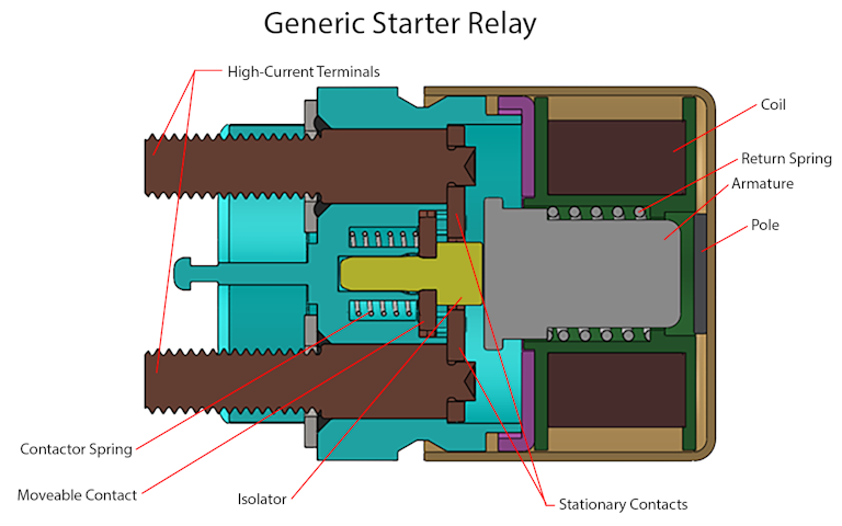
A starter relay, sometimes referred to as a starter solenoid, is used to switch the high current needed to turn the starter motor on an internal combustion engine. A generic starter relay is shown in cross section in Figure 1. This relay comprises an actuator (which is a simple solenoid) and a set of electrical contacts and spring(s), which provide the current carrying ability. The electrical contacts typically consist of one moveable contact and two stationary contacts. In Figure 1, the contactor portion of the relay is at left within the blue region of the part. The actuator (solenoid) is on the right. The solenoid interacts with the contactor through the isolator. The isolator provides both electrical and thermal isolation between the solenoid and contactor. The high-current electrical connections to the outside world are made with lug terminals, and the low-current connection for the solenoid coil (not shown here) is typically made with an environmentally sealed connector.
Figure 1: Generic Relay

When actuated, the armature is pulled to the right against the pole, and the contactor spring forces the moveable contact to engage the stationary contacts, completing the circuit. The contactor spring force determines the contact force, which in turn determines the contact resistance. When power to the coil is removed, the return spring forces the armature back to the home position. The return spring must provide enough force to overcome the contactor spring and all friction in the system as well as provide enough force overhead such that shock and vibration loads cannot inadvertently close the contacts.
Market Drivers and Associated Risks
The automotive market for internal combustion engine (ICE) starting technology is undergoing a change due to market pressures. Most substantively, the advent of start/stop engine technology requires a much longer operating life for the starting system components. This is a challenge for the high-current contactor. In this device, the contacts are subjected to arcing on both closure and opening, causing contact wear, and distributing arcing-related debris into the unit. As a result, the contacts have a finite lifetime. This lifetime is dramatically reduced as the starting current is increased.
Starting current is highest immediately upon closure. This inrush current peak can be more than five times the steady-state current during the start sequence. This is true even in the smaller-displacement ICEs that are becoming more common and will predominate in the future. The trend in ICE technology is toward lower displacement and higher performance. This has resulted in higher-compression engines that are oversquare (bore is larger than stroke). Both conditions can potentially raise the required starting torque. Another market driver that unintentionally raises the inrush current is the drive to lightweighting. This market driver has resulted in changes to the configuration of starting systems to remove excess cable length and reduce overall resistance of the starting circuit outside of the motor. This series resistance normally acts to limit inrush current, so reducing the resistance allows the inrush current to rise relative to the steady-state current. In one case, inrush current for a 1.3-liter ICE reached more than 900 A—a value 50% higher than expected for the starting system. During investigation into the higher-than-expected inrush value, TLX found that the main driver for the high inrush current was the low series resistance. The inrush current was found not to be dependent on the torque load on the starter motor to any great degree. In essence, the starter motor initially drew as much current as if it were stalled, if only for a very short period of a few milliseconds.
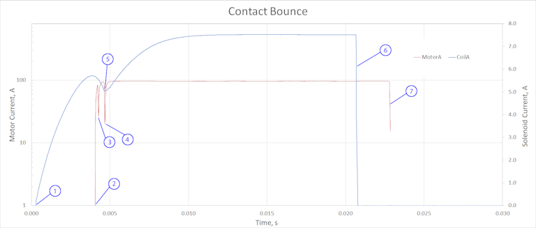
High inrush current also drives the risk of contact welding. During closure, there will inevitably be some minor contact bounce. An arc will form, and some melting of contact materials will take place. If enough melted area is present when the contacts finally close, the weld formed may be strong enough that the contacts will not open when the contactor is released. This is a failure mode that must be avoided because it poses a risk of collateral damage to the starting system and can be a safety risk to the vehicle operator and occupants. Figure 2 shows this bounce behavior.
Figure 2: Contact Bounce

The bounce test depicted in Figure 2 was conducted at a data sampling rate of 100 kHz. The red trace is the current in the starter motor circuit, which for purposes of this test was limited to 100 A. The blue trace is the solenoid current, which is read off the right-hand scale. At point (1), the solenoid is actuated, and current begins to rise. As the solenoid armature moves, first contact is made at (2), and starter current begins to rise. At (3) and (4) contact is lost again momentarily due to bounce. At (5) the solenoid armature has completed travel and is locked to the pole. At (6) the solenoid voltage is removed, and current falls rapidly. Once the magnetic field has decayed, the armature moves back toward its starting position, and at (7) the contacts are opened.
While increased inrush current reduces contact life and introduces a welding risk, a requirement for stop/start functionality dramatically increases the requirements for contact life. A vehicle without start/stop functionality that is primarily used for daily commuting may be started four to six times per day. Over a 15-year vehicle lifetime, this implies about 30,000 actuations. This number is very typical of lifetime requirements for ICE-powered vehicles where start/stop operation is not present. Where start/stop operation is present, the number of cycles required may be increased by a factor of 10 or more.
Download the complete white paper below.This article was originally published by TLX Technologies in March 2020
Want to explore design examples?
TLX Technologies is the go-to custom solenoid partner of the world’s top brands, first-tier suppliers, and OEMs