Design Constraints for EV Cooling Systems

January 5, 2021

Design Constraints

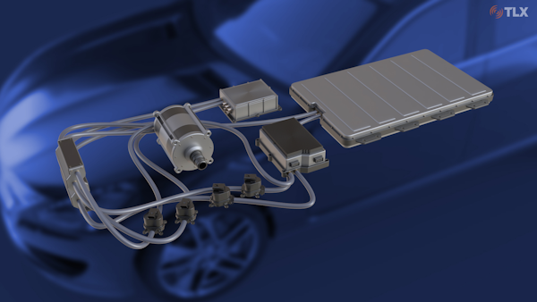
Designs for EV cooling systems are significantly more complicated and challenging than designs for ICE (Internal Combustion Engine) vehicles. EV cooling systems must accommodate several sources of heat generation in the vehicle (Figure 1) including:

  • Inverter electronics to control the motors used for the vehicle’s propulsion
  • Charging electronics (may or may not be integrated with inverter electronics)
  • Motor(s) used for vehicle propulsion and energy recovery
  • Vehicle propulsion (high voltage battery)

Figure 1

Setup With Car Background
EV Cooling Components

In a typical EV drivetrain, each of these heat sources may require maximum flows of eight to ten liters of coolant per minute. Sizing the cooling system to accommodate concurrent maximum flows results in energy and weight penalties in the pumping system. Precisely controlling the flow of coolant to each heat source based on temperature feedback is a more efficient solution. This allows for a smaller capacity pump because different optimal setpoints can be established for each heat source. For example, inverter electronics can be operated at their optimal temperature of 40°C to 65°C while motors or the battery can be cooled further or allowed to run warmer as performance demands dictate. In addition, waste heat from electronics and motors can be recycled to provide cabin heat and/or warm the battery during cold weather operation. This can avoid or minimize electrical resistance heating, greatly reducing parasitic electrical loads.

Therefore, an optimal EV cooling system configuration is significantly different and more complex than what is required for ICE cooling applications. The method for controlling the coolant flow between components is one critical aspect of this type of cooling system. The main attributes of such a proportioning method are:

  • Predictable relationship between setting and flow (lack of hysteresis)
  • Zero steady-state power at any setpoint (energy efficiency)
  • Capable of fully shutting off flow (leak-free off state)
  • Fail-safe condition when power is lost (e.g., full open)

Issues with Extant Solutions

The combination of the above attributes is not shared by any extant control valve. Specifically, valves that incorporate near-zero hysteresis, zero steady-state power, and a near-zero flow state are available (e.g., rotary valves actuated by stepper motors). In stepper-driven rotary valves, hysteresis is not truly zero but is determined by the repeatability of the step position and the backlash between the motor shaft and the valve element (backlash may be zero if the valve element is an integral part of the shaft). However, stepper-driven rotary valves have some undesirable attributes:

  • A rotating seal is required on the stepper shaft. Rotating seals are prone to leakage.
  • No fail-safe condition. If power is lost to the stepper, the valve will remain in the last-commanded position.
  • Stepper motors are relatively costly and can add substantial weight to a valve.
  • A stepper motor controller is required.
  • A position sensing/feedback system may be needed.

Figure 2

Discrete Proportional Valve
DPV Section

The DPV Concept as an Alternative

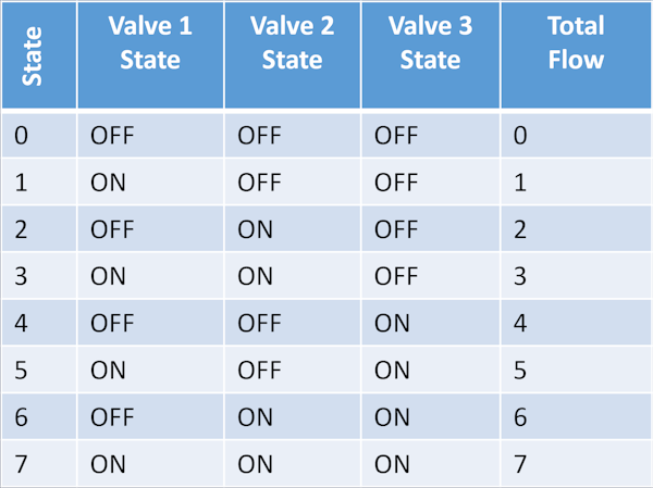
An alternative solution for enabling all the desired attributes while relying on a simpler valve actuation/control strategy is a discrete proportional valve (DPV). The DPV concept relies on intelligent combination of simple binary (on/off) solenoid valves (Figure 2). Two or more on/off valves with differing flow coefficients are combined in a single manifold to achieve a stepped approximation of a linear flow response. For example, a system of three valves gives 23 or eight possible flow states. The flow states can include a zero-flow state or a non-zero minimum flow state depending on the design. Table 1 shows the possible states for a 3-valve system where the individual valves are sized for flows of 1.0, 2.0, and 4.0 volumes per unit time. Figure 3 shows the resulting relationship between flow and valve command for such a system compared to the typical response of a continuous proportional valve.

Table 1

Three Valve DPV States
Three-Valve DPV States

Referring to Figure 3, the blue curve reflects the typical performance of a continuous proportional valve. At 0% command, the valve has some minimum flow due to bypass leakage. As the command is increased, there must be some built-in deadband to accommodate part-to-part variation in response. This is shown by the flat portion of the curve between 0% and 15% command. As command is further increased, the valve begins to open, and the flow response follows the lower blue curve. An upper deadband at 100% flow occurs, typically between 85% and 90% command. As the valve is commanded to reduce flow again, the response follows the upper blue curve. The difference between the upper and lower blue curves is the hysteresis of the system due to mechanical friction and magnetics. Hysteresis also increases the effective deadband at full flow.

Figure 3

Performance Curves
DPV and Continuous Proportional Valve Performance Curves

The orange curve in Figure 3 shows the response of a 3-valve DPV system. The response is stepped, and there is no hysteresis. By definition, a given command will always result in the same valve members opening, and thus the same flow coefficient. In addition, there is no requirement for either lower or upper deadbands. What appears to be a lower deadband is actually the controlled true off state. It can be designed as such or designed to be a minimum flow value such that there is always some flow through the system (to avoid pump damage, etc.).

The DPV concept in its simplest form does require steady-state power. However, by incorporating a latching solenoid design into the valve actuator, the steady-state power requirement can be eliminated. Latching solenoids can be constructed by using permanent magnets or other means to hold the actuator latched. This eliminates power draw in any given steady state.

A true zero-flow state is a native attribute of a DPV valve system (all valves off). Other implementations of proportional control can also provide effectively zero flow, however tight mechanical tolerances can be required, which raise the risk level related to debris sensitivity and wear. Tight mating tolerances also increase cost. The DPV concept achieves a zero-flow state without requiring this trade-off.

DPV Control

The control system to drive a DPV valve system can be implemented in essentially two ways:

  • The control system is embedded in the valve system. Analog or digital input is used to command the system.
  • Establish an electrical connection only to the DPV system. Control is centralized remotely.

Schema (1) requires some intelligence be built into the valve system as well as power electronics to control each valve via an on-valve control board. This DPV control board would require a minimum of only three incoming wires: power, ground, and signal. The control board would translate the desired state, communicated on the signal line, into commands to the valves. The control board will also provide for the fail-safe state if it detects a loss of power.

Schema (2) requires two wires for each valve in the DPV system. The control electronics can then be centralized. This increases the amount of wiring required but offers better environmental protection.

In an actual vehicle application, some of the benefits of both options may be realized by co-locating multiple DPV systems on a manifold and locating the control electronics close by. Such a configuration would also be desirable from a fluidics perspective.

The control electronics for a DPV system are inherently simple, requiring only a mapping of the desired flow to DPV state. The single complicating factor for DPV control is a result of the zero steady-state power. Opening a valve requires a forward current pulse; closing the same valve requires a reverse current pulse. The requirement for both polarities eliminates the possibility of a common ground and requires two independent connections to each valve. Even with remote electronics, however, the wiring requirements for a three-valve system are not prohibitive.

Conclusions

Adapting extant technologies to the new and ever-changing advancements in e-mobility is often not the best solution. For example, the cooling systems for internal combustion engines are relatively simple and are not designed to deal with the widely-varied cooling needs from multiple heat sources found in electric vehicles. Therefore, adapting that technology to electric vehicles is not the most efficient or effective solution and can be counter-productive in the quest for increasing energy efficiency.

The simplicity and design flexibility of the discrete proportional valve (DPV) provides advantages that match the unique needs of EV cooling and energy management systems. While the DPV does not provide for smooth control of output, but rather stepped control, it alleviates the need for deadbands and eliminates hysteresis completely, simplifying control algorithms. Importantly, it is also a power-efficient solution in line with the demands of next generation EVs. The DPV also has the potential to enable further efficiency gains by recycling heat that otherwise would be rejected to the environment.

TLX Technologies seeks to offer solutions that are designed and manufactured specifically for the e-mobility market. That is why TLX developed its discrete proportional valve (DPV). The DPV provides lightweight, customizable semi-proportional coolant flow with exceptional energy efficiency, a leak-free off state, fail-safe condition, and no hysteresis.
This article was originally published by E-Mobility Technology International in October 2020

Want to explore design examples?

TLX Technologies is the go-to custom solenoid partner of the world’s top brands, first-tier suppliers, and OEMs